IPTV Configuration Guide
IPTV Basic Configuration Guide
Distribution Type
AV Over IP
Overview
This guide will provide instructions for the configuration and setup of a basic IPTV system using a QIP series IPTV encoder, a QIP-D, or QIP-DVX IPTV decoder/controller, or IP-SDI 4i decoder. The devices will be connected to one managed network switch. This simple IPTV system will have two source channels available to a single decoder for viewing. The system may be easily expanded. Encoders may be added to provide additional source channels. Decoders may be added to accommodate more viewing locations.
The following will be required.
- QIP-HDMI 2, QIP-SDI 2, QIP-YPB2, or QIP-SDI HDMI IPTV encoder with two video sources
- QIP-D, QIP-DVX decoder/controller, or IP-SDI 4i decoder with connected video display
- PC or laptop computer with CR Toolbox software
- Layer 2 or Layer 3 managed network switch (PoE will be required for QIP-D and QIP-DVX decoder/controllers)
The steps involved will include the following.
- Download and install CR Toolbox software
- Configure the network switch
- Configure the encoder
- Create and upload the channel list to the decoder
CR Toolbox Software
The CR Toolbox software for PC will need to be downloaded and installed. CR toolbox will be required for uploading the channel list to the decoder. It is also used as a convenient way to view the status of the connected Contemporary Research products. The web pages for each CR product may be easily launched by double-clicking on the entry in the device list tab.
Getting Started
Connect the video sources to the QIP encoder and connect the video display to the decoder/controller or decoder. Connect an Ethernet cable from the network switch to the encoder, decoder/controller, or decoder, and to the PC.
The examples shown in this document will be using the default static IP network settings for the encoder and decoder/controller.
The PC should be assigned a static IP address in the range of 192.168.1.xxx with a subnet mask of 255.255.255.0. As an alternative, an address assigned by a DHCP server may be used provided it is the same range.
Configure Network Switch
IGMP
The network switch will need to be configured to enable Internet Group Management Protocol (IGMP). IGMP is the protocol used for communication from the decoders and the network switch to request forwarding of an IPTV stream and to cease forwarding an IPTV stream, or from the network switch to the decoders to request membership status.
It is beyond the scope of this guide to provide configuration instructions for any specific make or model of network switch. Contact Contemporary Research or the network switch manufacturer for technical assistance.
Below are some common settings for IGMP.
- Enable IGMP Querier
- Set the IGMP Querier address (set to address in same range as VLAN or follow manufacturer’s recommendation)
- Set IGMP Compatibility to IGMPv2 or Auto
- Enable IGMP Snooping
- Disable Forward Unregistered Multicast
- Enable Fast Leave on ports connected to decoders
- Disable EEE Green Ethernet
PoE
The switch should be configured to enable PoE if required for the ports that are connected to QIP-D or QIP-DVX decoder/controller units.
Configure the Encoder
The QIP encoder may be configured using the built-in web pages or the front panel menu system. The menu structure of the front panel menu system is similar to the web pages. The examples shown below are using the web pages.
Using CR Toolbox, select the QMODs/QIPs tab if it is not already selected. Double click on the name of the QIP encoder in the device list to launch the encoder’s web page in a browser. As an alternative, the encoder’s IP address may be entered in the address bar of a web browser. The encoder’s current IP address can be displayed on the front panel by holding the Setup button. The default IP address is 192.168.1.227.
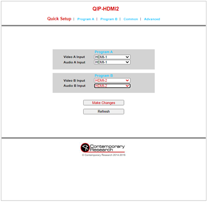
Select the Video and Audio Inputs
From the Quick Setup menu, select the desired video and audio inputs for Program A and Program B. By default, the video and audio source for Program B is set to None. Click on the Make Changes button to apply the new settings.
Enable Multicast
Multicast is not enabled by default. Navigate to the Program A web page, click on the drop-down menu for UDP Mode and select Multicast. Click on the Make Changes button to store the settings. Repeat the process for Program B.
Multicast IP Address and Port
The default multicast destination IP address and IP port number may be used for each program.
The QIP encoder’s output TS Mode is set to SPTS (single program transport stream) by default. Program A and Program B will each be an individual IPTV transport stream and have their own multicast destination address and IP port settings. It is acceptable for each program to have the same multicast destination address and a unique IP port number, or each program can have a unique multicast destination address and the same or unique IP port numbers.
Take note of the multicast destination address and port number for each program as this information will be required for configuring the decoder.
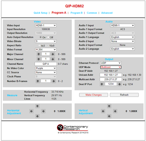
Channel Number and Channel Name
Each program is assigned a channel number and channel name. The channel number and name data is embedded in the transport stream for each program, but the information is not used directly by the decoder.
The QIP encoders only support two-part channel numbers. The valid range for the channel number is 1-0 to 999-999.
The channel name field supports up to seven characters.
Create and Upload the Channel List to the Decoder/Controller
Operation of the decoder requires that a channel list be created and uploaded and stored in NVRAM. The channel list is created and uploaded using CR Toolbox software.
The channel list includes information about each IPTV channel. The information for each channel includes the following.
- Channel Number - May be expressed as one-part or two-part
- Channel Name - Limited to seven characters
- Program Number - As specified in the encoder
- IP Mode - UDP or RTP
- IP Address - Destination IP Address as configured in the encoder, may be a Unicast or Multicast address
- Port Number - Destination IP Port as configured in the encoder
Create the Channel List
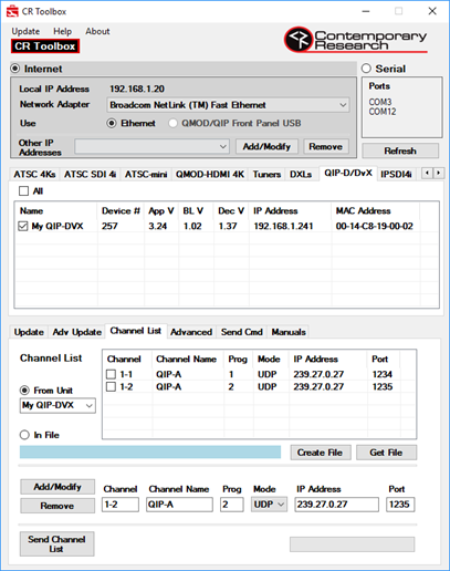
Launch CR Toolbox and allow a few moments for the software to populate the device lists. Select the QIP-D/DVX or IP-SDI 4i tab to display the decoder/controller or decoder.
In the bottom portion of the CR Toolbox window, click on the Channel List tab.
Follow the steps below to add the first channel to the channel list.
- In the Channel field, enter the channel number for Program A from the encoder configuration, the default is 1-1
- In the Channel Name field, enter the channel name for Program A from the encoder configuration, the default is QIP-A
- In the Prog field, enter the program number for Program A from the encoder configuration, the default is 1
- In the Mode drop-down menu, verify that UDP is selected
- In the IP Address field, enter the multicast destination address for Program A from the encoder configuration, the default is 239.27.0.27
- In the Port field, enter the destination IP port for Program A from the encoder configuration, the default is 1234
- Click the Add/Modify button to add the channel information to the channel list
Follow the steps below to add the second channel to the channel list.
- In the Channel field, enter the channel number for Program B from the encoder configuration, the default is 1-2
- In the Channel Name field, enter the channel name for Program B from the encoder configuration, the default is QIP-B
- In the Prog field, enter the program number for Program B from the encoder configuration, the default is 2
- In the Mode drop-down menu, verify that UDP is selected
- In the IP Address field, enter the multicast destination address for Program B from the encoder configuration, the default is 239.27.0.27
- In the Port field, enter the destination IP port for Program B from the encoder configuration, the default is 1235
- Click the Add/Modify button to add the channel information to the channel list
Upload the Channel List
Once the channel list is complete, click on the checkbox next to the decoder in the device list and then click on Send Channel List to upload the channel list to the decoder.
View IPTV Programming
The decoder/controller or decoder will not automatically begin receiving an IPTV stream after the channel list is uploaded. A channel command will need to be entered to view a channel. The command may be a simple channel up or channel down action from the front panel or Control web page. The channel number may also be entered directly from the Control web page.
Adding Additional Encoders
Additional QIP encoders may be added to increase the number of source IPTV channels. Each additional QIP encoder will need to be assigned a new IP address. The IP settings may be changed in the front panel Common menu. Once a new IP address has been assigned, repeat the steps in the previous section for configuring the encoder.
Each additional channel will need to be assigned a new channel number, channel name, multicast destination address and IP port.
Each additional channel will require a new entry in the decoder’s channel list. The updated channel list will need to be uploaded to each decoder.
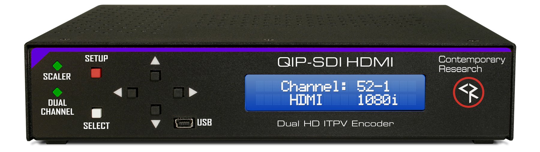
QIP-SDI HDMI IPTV Encoder
The dual-program QIP-SDI HDMI, with one SDI and one HDMI input, sets a new standard for sports, motion and digital signage encoding.
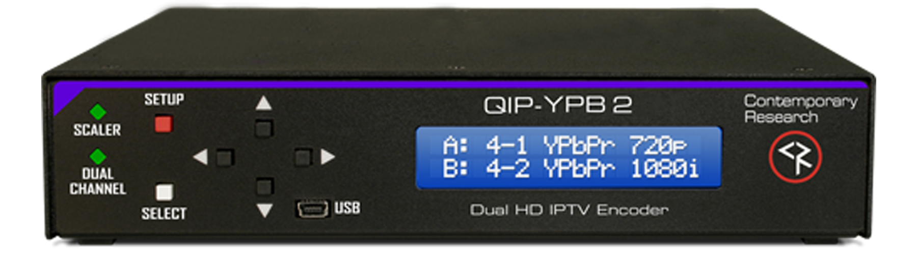
QIP-YPB 2 IPTV Encoder
The QIP-YPB 2 IPTV Encoder features dual-channel encoders that create MPEG-2 or H.264 IPTV streams from two separate video sources.
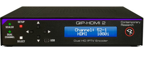
QIP-HDMI 2 IPTV Encoder
The dual-program QIP-HDMI 2, with two HDMI inputs, sets a new standard for sports, motion and digital signage encoding.
Adding Additional Decoders
Additional decoder/controllers or decoders may be added. Each decoder/controller or decoder will need to be assigned a new IP address. For the QIP-D and QIP-DVX decoder/controllers, the IP settings may be changed using the on-screen text menu. Press, hold, and release the Menu button to bring up the IP address. For the IP-SDI 4i, the IP settings may be changed in the front panel menu. Press Setup and navigate to the Network Setup Menu.
CR Toolbox will need to be refreshed or relaunched to add the decoder/controllers or decoders to the device list. The channel list will need to be uploaded to the addition decoder/controllers or decoders.
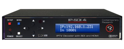
IP-SDI 4i IPTV Decoder
The IP-SDI 4i with SDI is an MPEG-2/H.264 IPTV decoder with internal scaler. The unit is part of a family of products from Contemporary Research that can be used to form an end-to-end IPTV distribution system.
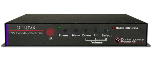
QIP-DVX IPTV Decoder/Controller
Contemporary Research’s latest IPTV decoder with incorporated display control, the QIP-DVX IPTV Decoder/Controller offers display control functionality through RS-232 or IR.
Technical Support
Contact Contemporary Research for technical support Monday through Friday 8:00 to 5:00 CT at 888-972-2728 or email [email protected]
IP-SDI 4i IPTV Decoder
The IP-SDI 4i with SDI is an MPEG-2/H.264 IPTV decoder with internal scaler. The unit is part of a family of products from Contemporary Research that can be used to form an end-to-end IPTV distribution system.
QIP-DVX IPTV Decoder/Controller
Contemporary Research’s latest IPTV decoder with incorporated display control, the QIP-DVX IPTV Decoder/Controller offers display control functionality through RS-232 or IR.