Basic Instructions for Integrating Display Express RF Control
Display Express is a very easy system to install and integrate, compared to other video distribution and control systems. Though it's really simple, it's often a new way of doing things for integrators. In this blog, we'll lay out the basic steps, covering topics we see arising from those new to the technology. If you get the basic steps right, you'll save a lot of time and effort caused by redoing the install correctly later on.
ICE-HE-DXL Display Control Center
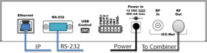
Install the ICE-HE-DXL Display Control Center first, as the unit sends a “Heartbeat” command over the RF network. If the RF data channel is correctly installed, all TV controllers have NET LED that will flash once a second. When you see the system “heartbeat” on the controller, you know it will respond correctly. Never use the RF In input-that's reserved for a legacy educational media system.
We advise using the RS-232 or USB port whenever the PC that sends the control commands is in the same rack. It often takes some time for the IT team to reserve a static IP address. If you are using IP from a Windows server or remote custom control such as AMX, Crestron and others, the local RS-232 is handy for testing when the system is being installed.
Ethernet
The Ethernet port requires a static IP address. The control protocol is identical for both RS-232, USB, and TCP. Commands are buffered, so you could use both ports at the same time. To define the IP port when connected to a DHCP network:
- Press the red Setup button
- Click the Left or Right arrow to view the Network menu, then click the white Select button
- Click the Down button to view IP Mode, use the right arrow to show DHCP, then press the Select button. This will set a DHCP address and capture the Submask and Gateway information.
- To set a Static address, set the IP mode to Static, Select, then press Up to see the IP address.
- Use the right arrow to select the last URL number, and use Up and Down to change the address (hold down the button to change numbers faster).
- Press Select to save the address
RS-232 Control
- Connect the RS-232 port, using a Null Modem cable, Female to Female
- 19200 baud, 8 bits, no parity, 1 stop bit, no flow control
USB Control
- The Mini USB port is typically used for a PC with Display Express software
- The port eliminates the need for a USB to RS-232 adapter cable
Combining
- Connect RF Out to an RF Combiner port, level is 45 dBmV, and is adjustable from the System/RF Level menu
- If combining with QMODs, set to 29 dB for QCA9-33 ports 1-8, or 14 dB for port 9.
- The micro control channel operates in the gap between channels 4 and 5, so it won’t affect other channels in your system
Testing
- When you send a command to the Display Control Center, the line below for the front-panel IP, USB or RS-232 text should flash Rx.
- The C (COM) icon should flash as well if the command’s basic structure is correct
- The N (NET) icon will flash twice each second
- If you haven’t set up a Display Express PC as yet, or finished your control system commands, you can download our IC Send software from our Product page. That will allow you to send control commands to test control operation over IP or RS-232. You can also control power and volume for all TVs using the Command menus on the ICE-HE-DXL.
TV Controller Installation
Setting the Device Number
In the next step, you’ll need to set up the device number for the ICC1-232 or ICC-IRX. Turn the enclosure so that the DIP switches are on the bottom as shown.
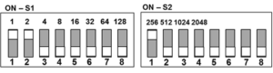
Switch S2 - Sets Zone number
- The four Zone switches add multiples of 256 to all addressing of thousands of controllers
- You can set up to 15 zones, from 256 to 3840
- At least one of switches 1-4 must be on
- Switches 5 and 6 must be off, 7 sets IR level higher for the ICC1-IRX
- VenueVizion systems using the onboard DX Lite control panel are limited to Zone 1
Switch S1 - Sets Unit Number
- This is a standard binary switch. Just add the value from the 8 switches to define a number between 1 and 255
- At least one switch must be on
Device Number
- The controller’s address will be the total of both switches.
- The address of the image above is 259 (3+256)
Geek Note: if you turn the enclosure around so the switches are at the top, you'll see that Switch 1 is now a binary expression where the first switch =128 and the last =1. Might be easier to use that way if you're more comfortable with binary numbers.
Zones
You can create up to 15 zones of controllers in this fashion. For small sites, you may want to set all controllers to Zone 1 (256). In larger installs, you can use the Zones to define pre-set groups for the controllers. Using Zones, you can send one command that is repeated by all controllers in that group.
- Zone 1 (256) - All controllers between 257 and 511 will respond to the command
- All Zones (4095) - All controllers will respond to the command
Most dealers will pre-configure the controller’s address before hanging displays - and some do this at the site. Either way, you need to plan the addresses and names you want to assign to each controller You can download a TV Installation spreadsheet here - Display Express TV Worksheet .
Code Sets
All TV Controllers will be shipped with the TV code set marked on a label so you can match the controller to the right TV. We repeat the instructions for the device address on that label – and there is space for you to add the TV address and location. They are shipped with a default number for testing, which you’ll change in the field.
ICC1-IR controllers have the full library of IR codes onboard. It will be set for the code you specified, but you can send a command to select a different code. ICC1-232 controllers have one code set installed. You can update or change the code later by updating the controller firmware.
ICC1-232 RS-232 TV Controller Installation
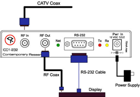
- Connect the system RF feed into RF In (the unit picks off the control channel and passes the rest on)
- Connect RF Out to the TV's Antenna/Cable input
- Connect the RS-232 cable to between the controller and TV - most use a DB9F null modem cable, a few use a DB9F to 3.5mm stereo mini cable (CR has both kinds)
- Add power to the unit, NeT LED should flash once per second if ICE-HE is active on the RF network
ICC1-IRX IR TV Controller Installation
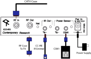
- Connect the system RF feed into RF In (the unit picks off the control channel and passes the rest on)
- Connect RF Out to the TV's Antenna/Cable input
- Connect the included IR emitter to the IR Out connector
- If you're using the Xantech CSM1 to sense the AC current, connect it to the CSM1 input (no other accessory needed)
- If you have an old analog tube TV, we have an optional CC-HSD that senses the EMI from the cathode. Connect to Tip+ and move the sensor cube around the back of the TV until the red LED lights
- Add power to the unit, NeT LED should flash once per second if the ICE-HE is active on the RF network
ICC TV Tuner/Controllers
You will set the address of the tuner via menus rather than switches, but the idea is the same. One menu sets the unit address from 1-99, and the next menu sets the Zone # from 1-15 (multiply the Zone # by 256). There is also a special mode that can define the complete address from an IR remote. Refer to the product manual for instructions.
TV Control Tips
- NEC RS-232 – One of the reasons we ask for TV makes and models when TV Controllers are ordered is there are several NEC code types that vary by model. For example, E-series TVs have one code type, but a slightly different set for 70” and TVs with the plug-in AVT tuner.
- Samsung Commercial TVs. The RS-232 code typeis the same for all commercial TVs, but some models use a DB9 connector and others use a 3.5mm jack
- Samsung Consumer Ex-Link. Some consumer sets use the Ex-Link 3.5mm RS-232 jack, and require a different code type.
- Samsung IR - the basic IR code set works for almost all Samsung TVs.
Need More Help?
Log in to the Contemporary Research Customer Support Portal for convenient access to open a ticket, view ticket history, connect with support agents, and view the Contemporary Research Knowledge Base.
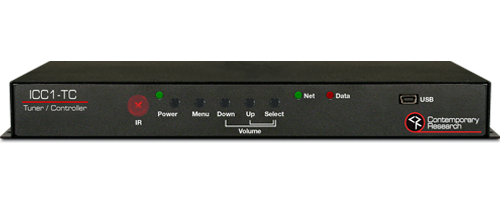
ICC1-TC Tuner/Controller
The ICC1-TC Tuner/Controller is an HDTV Tuner with integrated RS-232 to control HD monitors and projectors in a distributed CATV system with CR Display Express or third-party TV control.